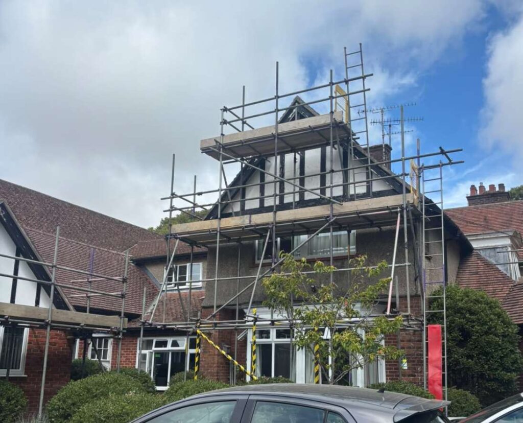
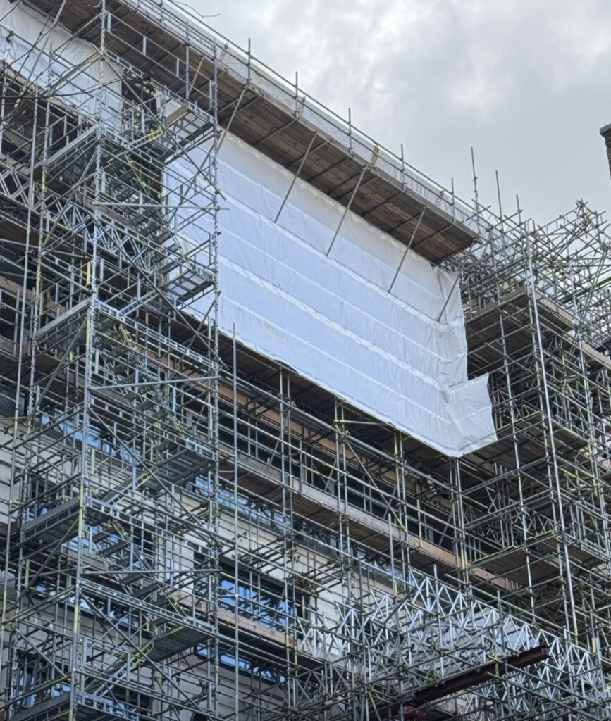
Scaffold leg loads are one of the most important checks behind a safe, stable access structure. Every standard transfers its share of the scaffold’s weight, people, materials and working equipment down to the base, so the ground or supporting structure must be capable of carrying that force without settlement, movement or damage.
We have planned scaffolds around homes, commercial premises, ports, restricted sites and difficult ground conditions for more than 20 years. The arithmetic is only one part of the task: a reliable assessment also considers the scaffold layout, intended use, bearing surface, weather exposure and any changes likely during the works.
A leg-load calculation should never be treated as permission to build an unverified scaffold. It is a planning tool that helps competent people select an appropriate arrangement, identify when sole boards or spreader solutions are needed, and recognise when a bespoke design or structural engineer’s input is essential.
What Is a Scaffold Leg Load?
A scaffold leg load is the vertical force imposed at the foot of an individual standard, commonly called a leg. That force is transferred through the base plate and, where used, a sole board or other load-spreading arrangement into the ground, slab, roof, bridge deck or supporting structure below.
Loads are often expressed in kilonewtons (kN), while site teams may also discuss kilograms or tonnes for simplicity. One kN is approximately equal to 102 kg of mass under gravity, but calculations should stay in kN so that the figures remain consistent with design information and bearing-capacity data.
The highest load is not automatically at every leg. A scaffold can load its standards unevenly because of bay lengths, lift heights, loading bays, hoists, bridging, cantilevers, temporary roofs, sheeting and the way materials are stored or handled.
Why it matters: if the bearing surface is too weak, a base can sink. Even small settlement may alter levels, loosen ties, change brace geometry and create risks that are not obvious from a quick visual check.
What Contributes to the Load on Each Leg?
Before calculating anything, we establish what the scaffold is expected to carry throughout its working life, rather than only what it weighs on erection day. This means allowing for the structure itself as well as the people, tools and materials that may be present during different stages of the project.
Dead load is the permanent weight of the scaffold components. Standards, ledgers, transoms, braces, boards, guardrails, toe boards, ladders, stair units, mesh and protective measures all contribute to it.
Imposed load, sometimes called live load, covers workers, tools, stored materials and work activity on platforms. The relevant scaffold class and duty loading need to suit the work; roofing access, brickwork, render removal and heavy refurbishment do not necessarily have the same loading requirements.
Additional and exceptional effects can materially change the design. These include loading bays, debris chutes, rubbish skips supported from the scaffold, hoists, temporary roofs, cladding, brick guards, netting and local concentrations of materials.
- The total self-weight of scaffold tubes, fittings and boarded lifts
- Platform duty loading for the planned task and storage arrangement
- Loads from access stairs, ladders, gates and hop-up brackets
- Wind effects and the additional weight or drag from sheeting and netting
- Point loads introduced by lifting equipment, beams or suspended arrangements
- Uneven distribution caused by irregular bays, returns and changes in elevation
Materials should not be stacked wherever space happens to be available. A designated loading bay may be required where supplies are landed or accumulated, because it has a defined purpose and is designed around more concentrated loads than a normal working platform.
For example, our commercial unit re-roof access work required the scaffold to support roofers’ access while keeping the occupied premises practical to use. On projects like this, the expected movement and temporary storage of materials must be discussed before erection, not decided after the scaffold is handed over.
The Basic Method for Estimating Leg Loads
A simple preliminary estimate starts by finding the total vertical load carried by a defined section of scaffold and dividing it between the standards that genuinely support it. This can be useful for identifying obvious bearing concerns, but it does not replace a scaffold design calculation because real structures rarely distribute force perfectly evenly.
Start with the supported scaffold area
Identify the lift or lifts, bay lengths and width that feed load into the legs being considered. A standard in the middle of a long, fully boarded run may support a larger tributary area than one at an end, beside a return or next to an opening.
Add dead and imposed loads separately
Use verified component weights and the specified platform load, rather than guesses based on a photograph or an assumed number of boards. Include all planned accessories, and do not overlook the fact that several lifts may be loaded at the same time.
Apply the correct design approach
A competent designer considers the applicable configuration, load combinations, factors and limitations of the scaffold system. For a standard-compliant arrangement, this may follow recognised configuration guidance; for non-standard work, it should be addressed in a bespoke design.
Allocate load realistically
Dividing the total by the number of legs is only a rough screening exercise. The calculation needs to account for tributary areas, eccentric loading, discontinuities, loading bays and components that channel force to particular standards.
As a very simplified illustration, assume a small section has an assessed vertical load of 24 kN and four legs carrying it equally. The initial average is 6 kN per leg, but it would be unsafe to assume every leg is therefore limited to exactly 6 kN in service, especially if materials are stacked on one side or a hoist changes the force path.
That preliminary 6 kN figure is then compared with the allowable capacity of the supporting ground or structure after considering the actual bearing area. It is the start of the conversation, not the completed design.
From Leg Load to Ground Pressure
A base plate prevents the narrow end of a standard from bearing directly into the surface, but its area may still be too small for soft or variable ground. Sole boards spread the load over a much larger area, reducing the pressure applied to the surface beneath.
The basic relationship is straightforward: ground pressure equals leg load divided by bearing area. If a leg load is 6 kN and the effective bearing area is 0.30 m², the nominal pressure is 20 kN/m².
That result cannot be judged in isolation. The ground’s allowable bearing capacity may be affected by soil type, moisture, previous excavation, made ground, nearby drainage, buried services, frost, vehicle traffic and the condition of paving or slabs.
Use the effective area, not the assumed board size
A warped, split or poorly supported sole board does not reliably spread force across its full footprint. The board must sit flat, be sound, be adequately sized and have continuous support from the surface below.
We regularly see the difference between apparently firm ground and ground that performs reliably under sustained load. Freshly backfilled trenches, grass verges, asphalt edges and paving laid over weak sub-base are all reasons to pause and assess rather than relying on appearance.
Checking the Supporting Surface Before Erection
Leg loads matter equally when the scaffold is not on soil. A courtyard slab, basement roof, suspended floor, canopy, garage roof or public footway may have a limited load capacity that needs confirmation from the building owner, principal contractor or a structural engineer.
Ground-level checks should look for changes in level, soft patches, voids, underground chambers, drainage runs and signs of recent disturbance. We also consider where water will run during heavy rain, because pooling around bases can soften some surfaces and make inspection more difficult.
Structural-support checks need more than a visual opinion. Where standards land on a roof, deck or suspended slab, the scaffold team needs confirmed information on the structure, its load paths and any restrictions on where loads can be introduced.
Public and operational areas bring further considerations, including impact protection, segregation and avoiding obstruction. A solution may need beams, kentledge, bridging or a different access strategy where the desired base locations are unsuitable.
Specialist arrangements are particularly sensitive to force paths. A cantilever and hanging scaffold transfers load through designed beams, anchors or a supporting structure rather than simply into the ground, so it should be based on project-specific design information.
When a Simple Calculation Is Not Enough
Some scaffold configurations can be erected to recognised standard guidance when every requirement is met. Once the layout departs from that guidance, however, a competent temporary works design process becomes increasingly important.
Seek a scaffold design or engineering review where the scaffold includes significant loading, unusual geometry or support conditions that make the force path uncertain. It is better to identify this during the survey than to discover it after materials have arrived on site.
- Loading bays, hoists, gantries or lifting beams
- Temporary roofs, extensive sheeting or large brick guards
- Cantilevers, bridges, suspended sections or scaffold over conservatories
- Very tall, exposed or irregular structures
- Scaffold founded on roofs, decks, cellars or unknown ground
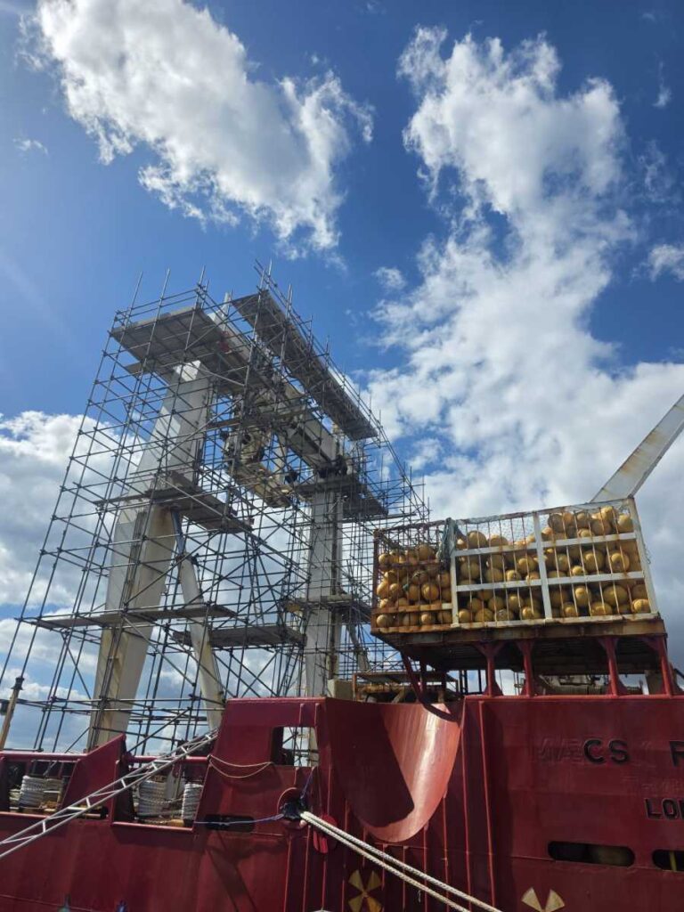
- Marine, tidal or live operational environments
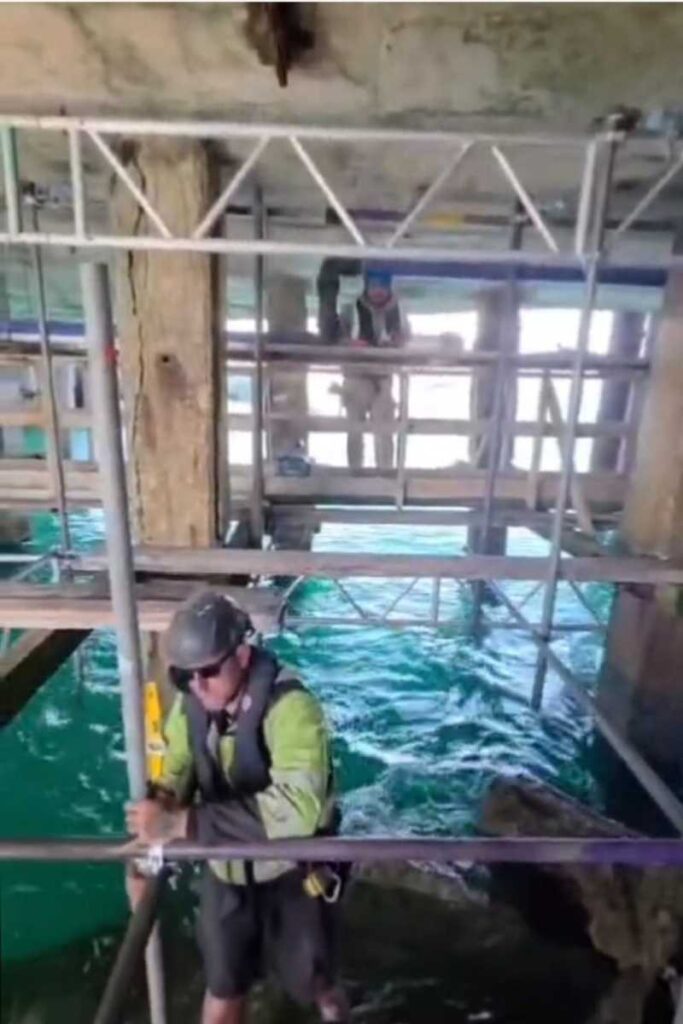
Marine work is a good example of why familiar-looking scaffolds can demand more detailed assessment. Our jetty underside scaffold installation involved a demanding environment where supporting members, access restrictions and operational conditions had to be considered together rather than treating leg loads as a standalone number.
For projects involving designers, contractors and multiple trades, the calculation should form part of the wider risk assessment, method statement and handover information. Clear communication prevents an approved scaffold from being altered informally or loaded beyond the purpose for which it was erected.
Common Mistakes That Increase Scaffold Risk
The most common error is treating an average load as a maximum load. An average can hide the effect of a loaded bay, a material stack, uneven ground or a change in scaffold geometry.
Another frequent issue is using unsuitable sole boards, or omitting them because the surface looks hard. Base plates on block paving, soft verges, asphalt or ground near excavations need especially careful consideration, and damaged timber should never be used as an improvised bearing solution.
Changes made after handover can also invalidate earlier assumptions. Adding a debris chute, fitting more sheeting, moving a hoist, storing roof tiles on a lift or removing a tie may change loads and stability, so the scaffold contractor should be contacted before modifications are made.
Good housekeeping is part of load control. Keep materials within agreed limits, spread them as intended, avoid local piles at platform edges, and ensure that only authorised people alter the scaffold.
Inspection, Monitoring and Changing Conditions
Calculating the initial load is not the end of responsibility. Scaffolds require inspection by a competent person before first use, at appropriate intervals, and after events or changes that could affect safety, in line with the project’s legal duties and recognised UK guidance.
During routine checks, look at the bases as well as the visible platforms. Settlement, leaning standards, crushed sole boards, standing water, cracked paving, loose base plates and altered ties are warning signs that should be reported immediately and investigated before use continues.
We plan the full process from survey and erection through inspection, adaptations and dismantling, because project conditions often change. Our scaffold quality policy reflects the importance of controlled work, competent checks and clear communication throughout that process.
What We Get Asked…
Can we calculate scaffold leg loads by dividing the total weight by the number of legs?
It can provide a basic average for early planning, but it is not enough for a final assessment. Loads are often uneven, and a competent calculation must consider the actual layout, tributary areas, platform loading and local features such as hoists or loading bays.
Do all scaffolds need sole boards?
Not necessarily, but they are commonly needed to spread loads and protect the supporting surface. The decision depends on the leg load, base plate area and verified condition and capacity of the ground or structure below.
Who confirms whether a roof or slab can support scaffold legs?
The building owner or principal contractor should provide reliable structural information, and a structural engineer may need to assess the supporting construction. Scaffolders should not assume that a roof, canopy or paving slab is suitable merely because it appears substantial.
What should happen if a scaffold base starts to sink?
Stop using the affected area, prevent access where necessary and contact the scaffold contractor without delay. Do not pack beneath a settling leg or make unauthorised adjustments, as the cause and wider stability need competent assessment.
Our Final Thoughts
Calculating scaffold leg loads means understanding how every part of the structure transfers force to the ground or supporting building. A sound estimate combines scaffold weight, working loads and local concentrated loads, then checks that the bearing arrangement can safely spread that force.
For straightforward work, early discussion helps us select the right scaffold and prepare the base properly. For complex, heavily loaded or unusually supported scaffolds, a site-specific design is the responsible route.
If you are planning roofing, refurbishment, maintenance or specialist access work across Dorset and the surrounding area, speak with our team before the scaffold is erected. We can assess the site, clarify likely loading requirements and provide a safe, practical access solution matched to the job.